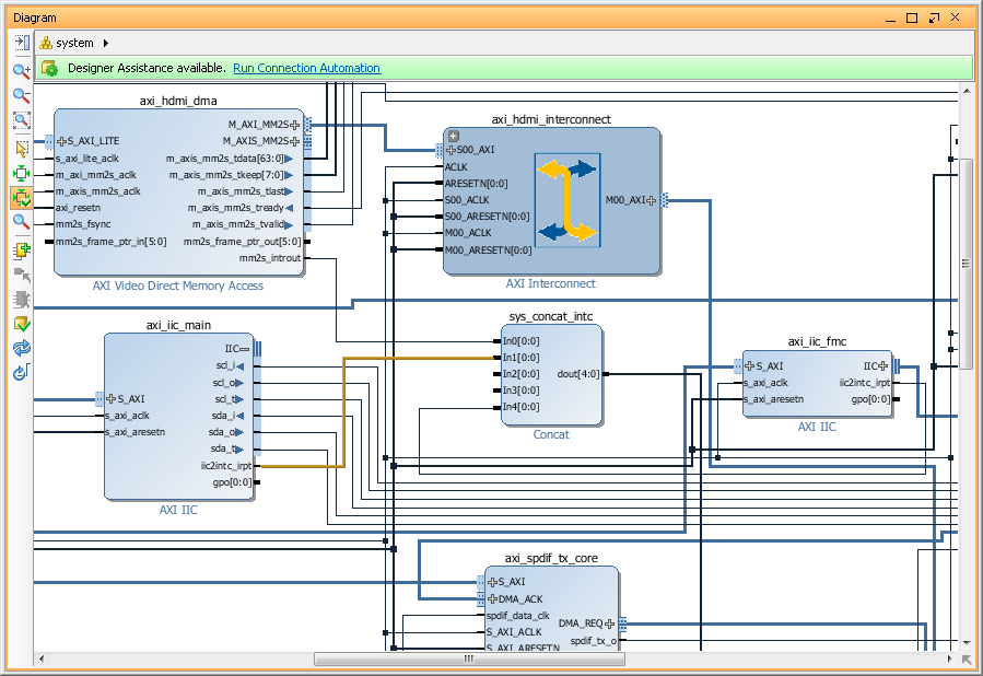
I finally figure it out why Analog Devices reference design create/generated in Vivado 2014 by script(obviously updated to use new IP's, otherwise it didn't assemble 'Block Design' at all) didn't work. Reason is changes in Xilinx Concat IP, which used in reference design to concatenate interrupt signals from VDMA and I2C IP blocks to Zynq's F2S interrupt bus.
So, now in 2014.1, we got version 2.0 of it and it preserve the order of input signals on the output. Which means we must either change inputs order or change interrupt numbers in DTS.
So, for AD reference design generated in Vivado2014.1 interrupts are:
As of today, 25 May 2014, to create HDL design for ADV7511 from scratch, we have to use Vivado 2013.4, even though Vivado 2014.1 is already available. The reason is some changes in a Xilinx IP's (which I didn't had a chance to figure out yet) prevent HDL design from build/work properly.
First step is to download HDL libraries and projects from AnalogDevices repositories on a github: https://github.com/analogdevicesinc/hdl. You can clone it or download a ZIP. I will download a ZIP and extract 'hdl-master' in my Projects/FPGA/ folder on Windows7 machine.
Second step is to build a few Analog Devices IP required to create ZedBoard HDMI design. Run Xilinx Vivado 2013.4, open a TCL console, change directories and 'source' a .tcl scripts. For example, to build AXI_CLKGEN IP:
cd c:/Projects/FPGA/hdl-master/library/axi_clkgen
source ./axi_clkgen_ip.tcl
After script finish, close created project and build the next. For ZedBoard we have build the next IP's:
hdl-master/library/axi_clkgen
hdl-master/library/axi_hdmi_tx
hdl-master/library/axi_i2s_adi
hdl-master/library/axi_spdif_tx
hdl-master/library/util_i2c_mixer
After we done with all required IP's, we can build ADV7511 reference design for ZedBoard. In a Tcl Console change directory to ADV7511 and run 'system_project' script.
cd c:/Projects/FPGA/hdl-master/projects/adv7511/zed/
source ./system_project.tcl
Script will create block design, run synthesis and implementation, generate bitstream and even export software to SDK(without opening it). This was the case on my system - everything went smoothly. We are done with Vivado and can close it.
We have to create HDL in Vivado 2013.4, but later we can import created project into Vivado 2014.1 and update it to use latest Xilinx IP's.
Let's build a FSBL. We need very typical Zynq first stage boot loader and I covered creation of it before, so now just a short description:
Run XSDK.
Create new 'Hardware Platform Specification' project (I named it 'ZedBoard-HDMI-HW') and specify HW created in a previous step.
Create Application project (named 'ZedBoard-HDMI-FSBL') using our new 'Hardware Platform' and select to create new BSP for it. Don't forget to use 'Zynq FSBL' template. Build it if this not done automatically.
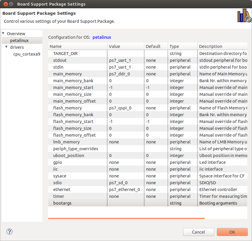
Next step is to create PetaLinux BSP. This is also very typical PetaLinux BSP, just don't forget to change 'Configuration' to reflect ZedBoard configuration and name it 'ZedBoard-HDMI-petalinux_bsp'.
We are done with Xilinx SDK. You can close it.
Next step is to create PetaLinux project and set 'hardware description'. I will call it 'ZedBoard-HDMI' Petalinux project:
petalinux-create -t project -n ZedBoard-HDMI
cd ~/Projects/ZedBoard-HDMI-petalinux_bsp/
petalinux-config --get-hw-description -p ../ZedBoard-HDMI/
cd ~/Projects/ZedBoard-HDMI/
rm -r hw-description
Now, as of today, ADV7511 Linux driver not in a mainstream kernel. So, we need to get Kernel from Analog Devices repository with appropriate patches. Current version is 3.14.0. Let's clone it, and checkout 'xcomm_zynq' branch.
cd ~/Projects/
git clone https://github.com/analogdevicesinc/linux.git analogdevices-kernel
cd analogdevices-kernel/
git checkout xcomm_zynq
Create necessary directories and copy 'xcomm_zynq' branch to our PetaLinux project directory.
cd ~/Projects/
mkdir ~/Projects/ZedBoard-HDMI/components
mkdir ~/Projects/ZedBoard-HDMI/components/linux-kernel
cp -a analogdevices-kernel ~/Projects/ZedBoard-HDMI/components/linux-kernel/
Run 'petalinux-config' and change kernel to 'analogdevices-kernel' and system boot device to 'SD card'.
cd ZedBoard-HDMI
petalinux-config
Next we need to configure Linux kernel for PetaLinux and we need to enable all options required by ADV7511. AnalogDevices kernel support special configuration option 'zynq_xcomm_adv7511_defconfig', but we cannot run it with PetaLinux. So, we have to pre-configure kernel separately ('make ARCH=arm zynq_xcomm_adv7511_defconfig') and just copy resulted config into 'ZedBoard-HDMI/subsystems/linux/configs/kernel'. So, I did it and also copied it into PetaLinux Kernel configs directory '/opt/petalinux-v2013.10-final/etc/template/project/template-zynq/subsystems/linux/configs/kernel'. So, I can later reuse it. Also notice that kernel default config file have dot in the front and PetaLinux files don't.
Anyway, here is link to my resulted kernel config file: https://blog.idv-tech.com/wp-content/uploads/2014/05/config_hdmi_3_14.config
We also, have to modify 'devices tree' generated by PetaLinux for our project. AnalogDecices Linux kernel have template for ZedBoard which you can find in 'arch/arm/boot/dts/zynq-zed-adv7511.dts', so we basically have to copy missing devices from AD into our tree.
Link to my resulted DTS file for ZedBoard: https://blog.idv-tech.com/wp-content/uploads/2014/05/adv7511_dts.config.
We are basically done. At this point you my want to modify PetaLinux project, for example, include Qt5 library and test app to check frame buffer device later. I covered this topics in my previous post, so I wont repeat it here.
Build Petalinux project, create BOOT.BIN and copy it together with Linux image file 'image.ub' on SD card:
Insert SD card into slot of ZedBoard and turn it on. During boot kernel should detect ADV7511(hdmi) and ADAU1761(sound) devices and create '/dev/fb0' device.So, below partial bootlog from my ZedBoard:
This is basically it - once you have a framebuffer device you can start using it. So I ran my Qt5 test app and it worked. We obviously don't have any hardware acceleration with this HDL design, but we got basic FB device and HDMI output. Congratulations!
A small, step-by-step tutorial on how to create and package IP. Just as an example, I will create 3-to-8 decoder IP in Xilinx Vivado 2014.1 and connect it to Zynq SPI chip select pins. This is not a Verilog tutorial, so I will give a minimum information required to create Verilog sources.
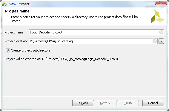
Run Xilinx Vivado and create new RTL project - name it Logic_Decoder_3-to-8; Specify Verilog as target language; also specify Zynq-7000 for a part family.
Next step to create IP source file. To do it click on 'Add Sources' in 'Project Manager' group in the Vivado project 'Flow Navigator'.
In a 'Add Sources' dialog select 'Add or Create Design Sources'.
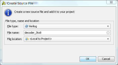
Then 'Create File...', specify new 'File Name' and click 'Ok' and 'Finish' buttons to close dialogs.
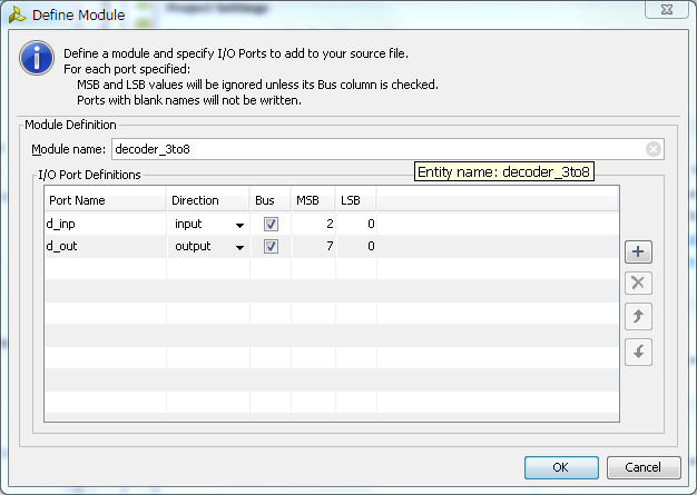
Next, Vivado will open 'Define Module' dialog where we have to specify inputs and outputs. Since we are creating 3 to 8 decoder, set type of input and output as 'Bus' and set appropriate bus width. Set port names to whatever makes more sense to you, but remember that 'in' and 'out' are reserved words, so you have to be a little creative here. Click 'Ok' close dialog.
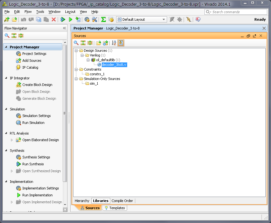
Now, in a sources window of the Vivado, you can see Verilog source file we just created. Open it.
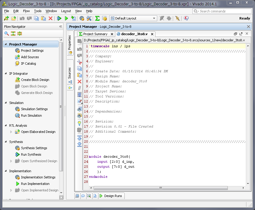
This is just a empty source file created using template, but it already have our module input and output defined and all we need to do is to modify it to do an actual address decoding. Below is the one possible solution to such problem.
Make changes to the source and save it. Now you can run simulation and synthesis and analize the resulted design, but I will skip it to make this tutorial simpler. I also using this very simple verilog module and know it works, but still did verification on it so can just copy-paste it.
Now, let's package it. In a 'Tools' menu of the Vivado select 'Create and Package IP...'. Later select 'Package your current project' option, include '.xci' files and 'Finish' new IP creation.
Change IP identification information if you wish, as well as, any other property for new IP.
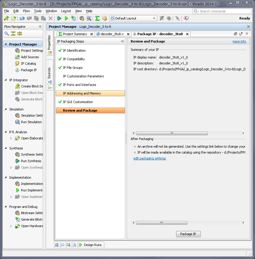
After you done with changes, click on 'Review and Package' menu on the bottom of the list and then click in 'Package IP' button.
We are done with this IP, close this project.
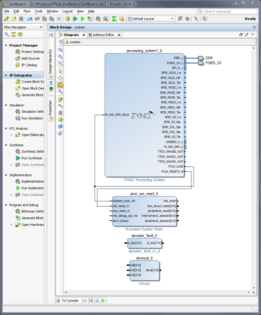
Now lets use our new 3-to-8 decoder IP. Just for example, I will create new, very basic Zynq design for ZedBoard and will decode one of it's SPI port outputs to 8. And will make them external on one of the ZedBoard PMOD connector. I will not cover creation of the Zynq block design, since I did it in my previous posts.
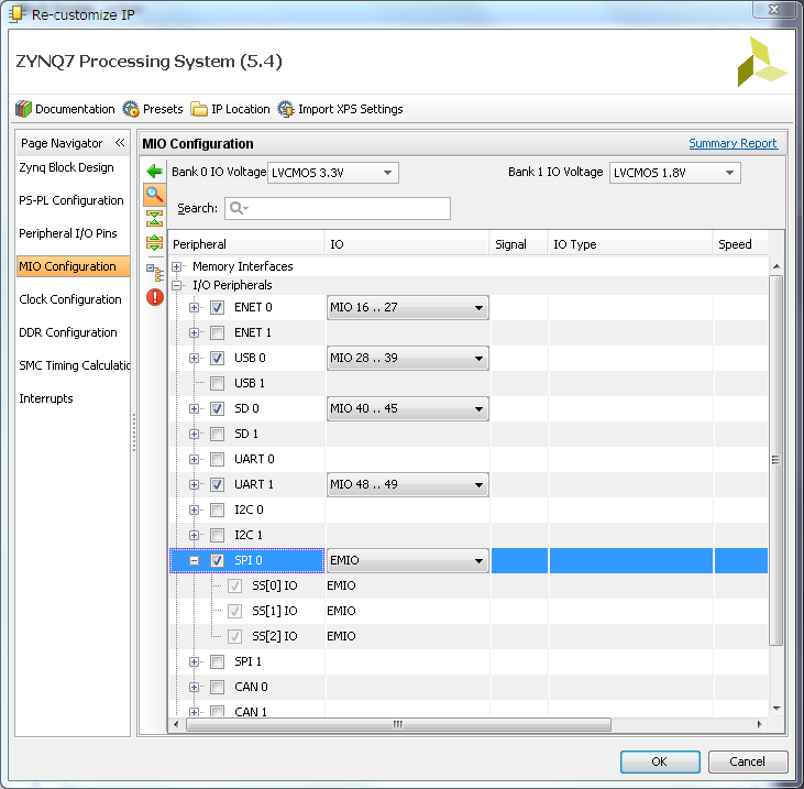
So, below my simple Zynq block design. Now, I have to enable SPI port. Double click on 'Zynq processing system', go to 'MIO Configuration' and enable 'SPI0' port. As you can see it can only have maximum 3 Slave Select (or Chip Select) pin and sometimes its not enough.
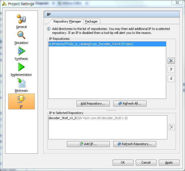
Next we need to add our 3-to-8 decoder module to block diagram, but before we can do it, we must add it's repository to our project IP manager. So, in a 'Tools' menu select 'Project Settings' and then click on 'IP' icon.
In 'IP' management dialog click on 'Add Repository...' button and specify our decoder IP project folder. Vivado will scan it, should find decoder IP and add it in found IP list. Click 'Apply' and then 'Ok' to close dialog.
We can add decoder IP to our block diagram. Click on 'Add IP', typo decoder IP name and add it.
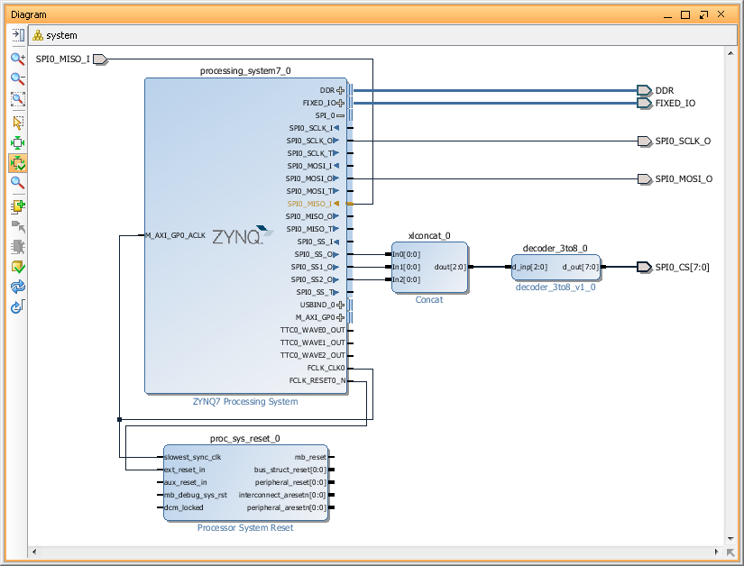
Now we have to connect 3 SPI SS outputs to our decoder input, but we can't. Problem is that decoder inputs treated as a 'bus' and SPI SS outputs as individual 'wires'. One of the possible solution is to concatenate individual wires. In order to do it add Xilinx 'Concat' IP and modify it, so it will have 3 inputs.
Now we should be able to connect all blocks together. Specifically, connect SPI0_SS0, SPI0_SS1 and SPI0_SS2 to 'Concat' block input 0,1 and 2. Them, connect 'Concat' output to our 3-to-8 decoder IP and finally make decoder outputs 'External'. I will also rename output port to 'SPI0_CS'.
This is basically it. Now we have to create 'constraints' file and specify in it Zynq PACKAGE_PIN for some or all pins of the 'SPI_CS0' port. For example you may want to export only 4 CS pins. Something like this:
Later, in a software project, you will need to enable special option for SPI driver to use 'Slave Select' pins as encoded address. But that is part of another tutorial, but this one finished. Good luck!