Howto create and package IP using Xilinx Vivado 2014.1

A small, step-by-step tutorial on how to create and package IP. Just as an example, I will create 3-to-8 decoder IP in Xilinx Vivado 2014.1 and connect it to Zynq SPI chip select pins. This is not a Verilog tutorial, so I will give a minimum information required to create Verilog sources.

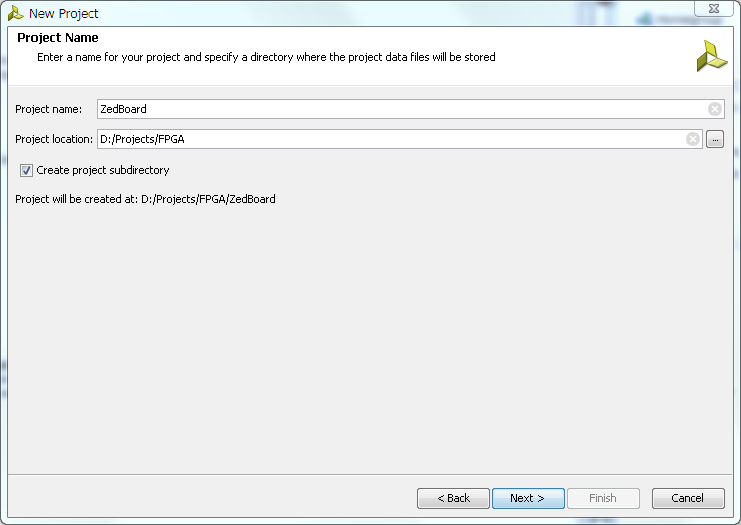
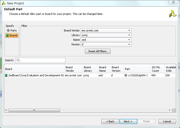
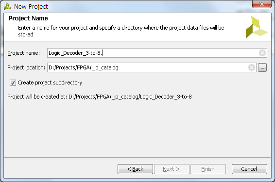
  1. Run Xilinx Vivado and create new RTL project - name it Logic_Decoder_3-to-8; Specify Verilog as target language; also specify Zynq-7000 for a part family.
  2. zynq14_1

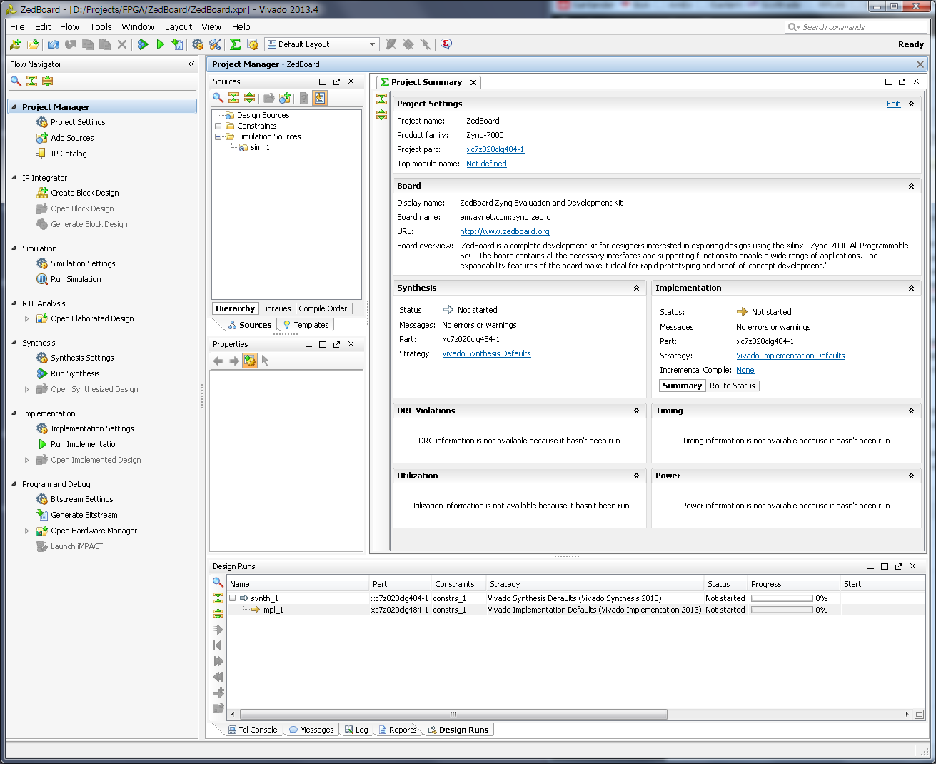
  3. Next step to create IP source file. To do it click on 'Add Sources' in 'Project Manager' group in the Vivado project 'Flow Navigator'.
  4. In a 'Add Sources' dialog select 'Add or Create Design Sources'.
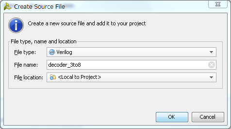
  5. Then 'Create File...', specify new 'File Name' and click 'Ok' and 'Finish' buttons to close dialogs.
  6. zynq14_2

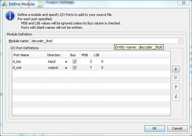
  7. Next, Vivado will open 'Define Module' dialog where we have to specify inputs and outputs. Since we are creating 3 to 8 decoder, set type of input and output as 'Bus' and set appropriate bus width. Set port names to whatever makes more sense to you, but remember that 'in' and 'out' are reserved words, so you have to be a little creative here. Click 'Ok' close dialog.
  8. zynq14_3

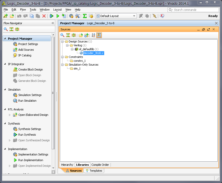
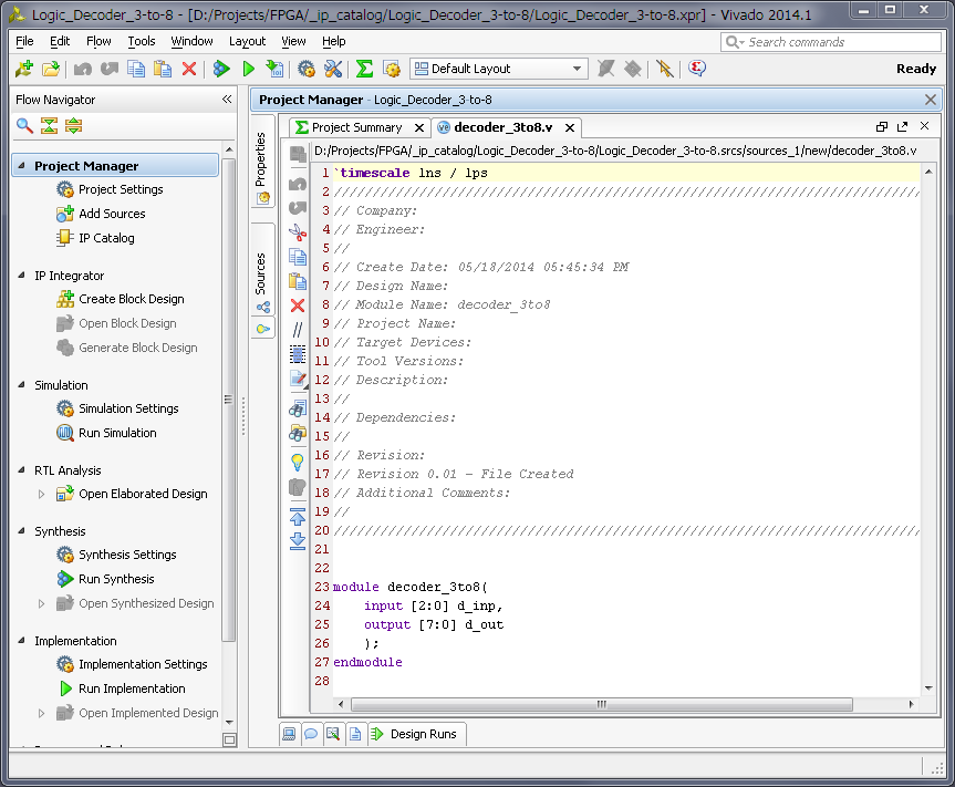
  9. Now, in a sources window of the Vivado, you can see Verilog source file we just created. Open it.
  10. zynq14_4

  11. This is just a empty source file created using template, but it already have our module input and output defined and all we need to do is to modify it to do an actual address decoding. Below is the one possible solution to such problem.
  12. zynq14_5

    module decoder_3to8(
        input [2:0] d_inp,
        output [7:0] d_out
        );
        
    assign d_out = (d_inp == 3'b000) ? 8'b00000001 :
                   (d_inp == 3'b001) ? 8'b00000010 :
                   (d_inp == 3'b010) ? 8'b00000100 :
                   (d_inp == 3'b011) ? 8'b00001000 :
                   (d_inp == 3'b100) ? 8'b00010000 :
                   (d_inp == 3'b101) ? 8'b00100000 :
                   (d_inp == 3'b110) ? 8'b01000000 :
                   8'b10000000;
        
    endmodule
    
  13. Make changes to the source and save it. Now you can run simulation and synthesis and analize the resulted design, but I will skip it to make this tutorial simpler. I also using this very simple verilog module and know it works, but still did verification on it so can just copy-paste it.
  14. Now, let's package it. In a 'Tools' menu of the Vivado select 'Create and Package IP...'. Later select 'Package your current project' option, include '.xci' files and 'Finish' new IP creation.
  15. Change IP identification information if you wish, as well as, any other property for new IP.
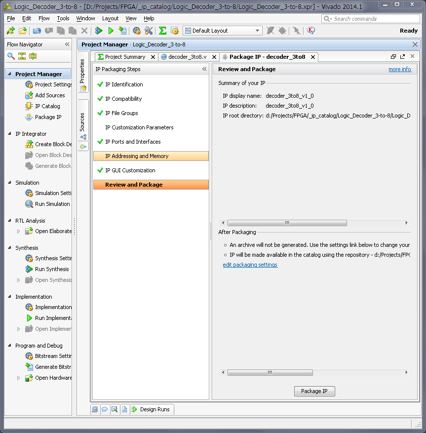
  16. After you done with changes, click on 'Review and Package' menu on the bottom of the list and then click in 'Package IP' button.
  17. zynq14_7

  18. We are done with this IP, close this project.
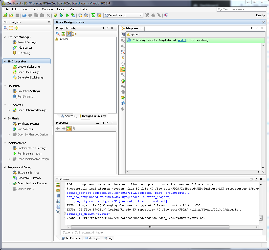
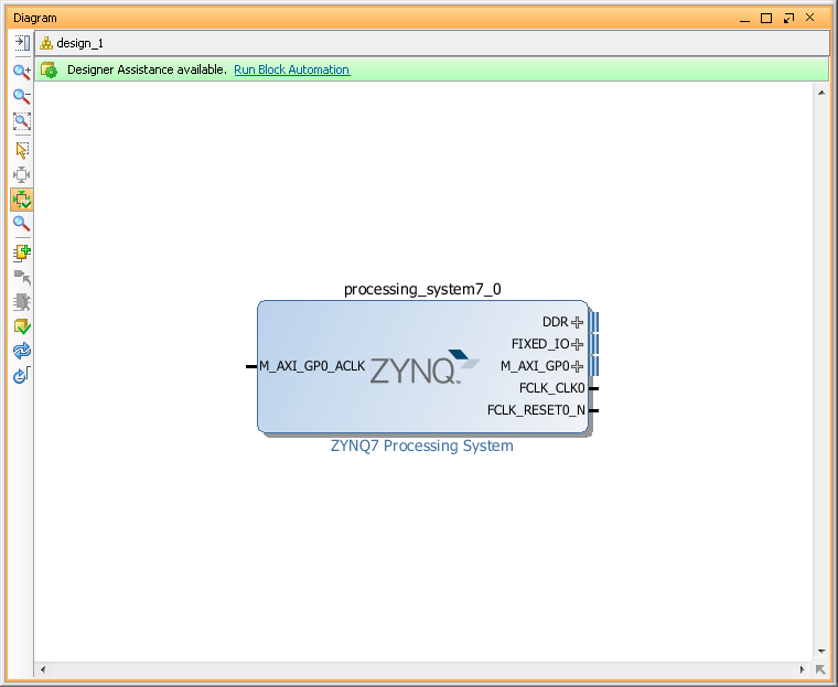
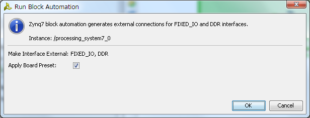
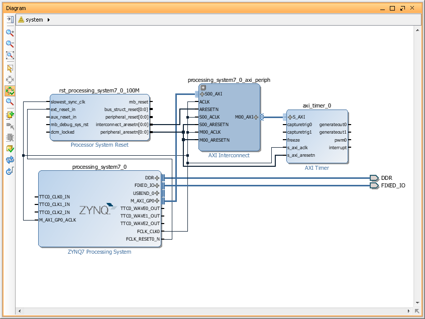
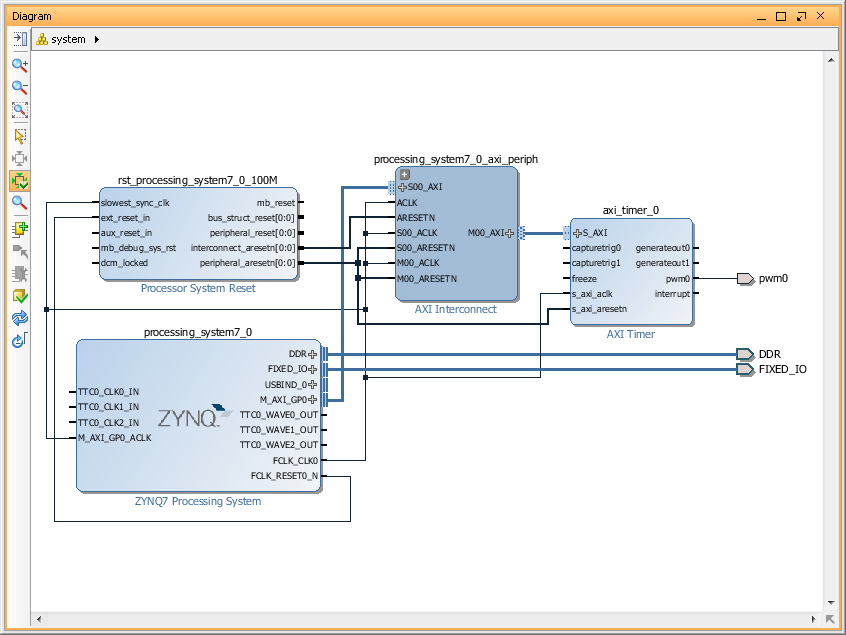
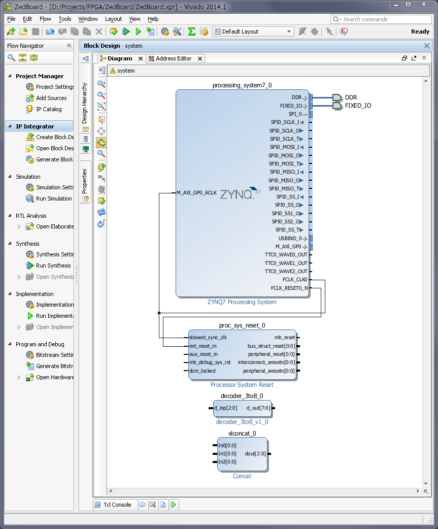
  19. Now lets use our new 3-to-8 decoder IP. Just for example, I will create new, very basic Zynq design for ZedBoard and will decode one of it's SPI port outputs to 8. And will make them external on one of the ZedBoard PMOD connector. I will not cover creation of the Zynq block design, since I did it in my previous posts.
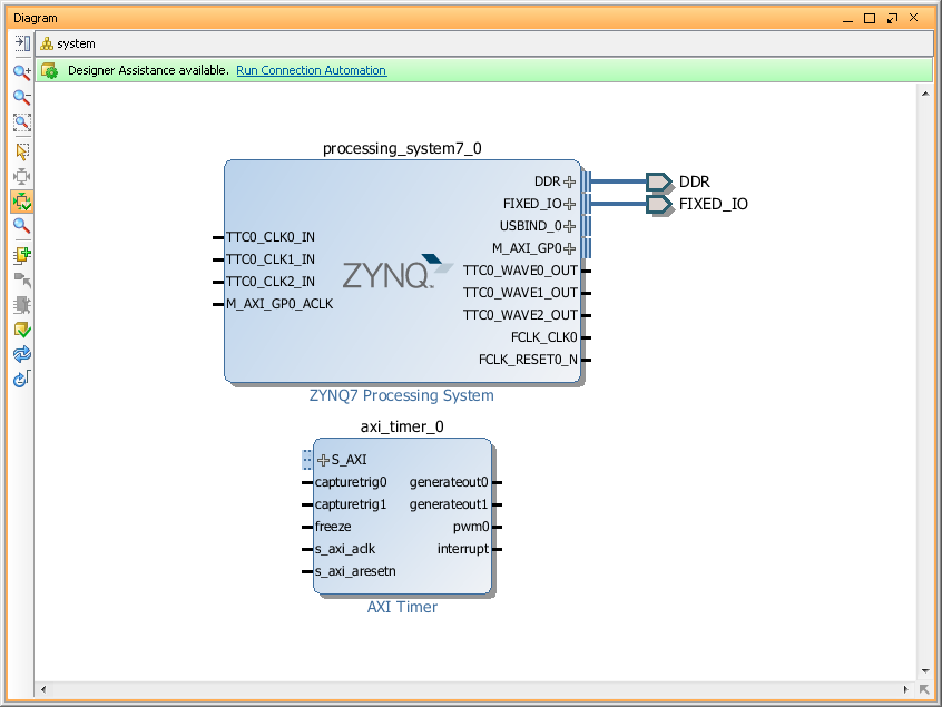
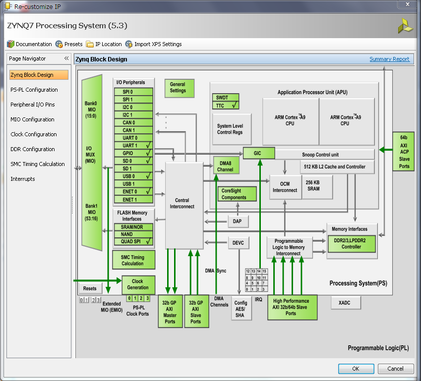
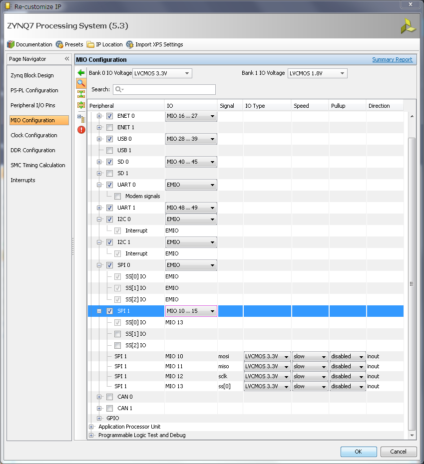
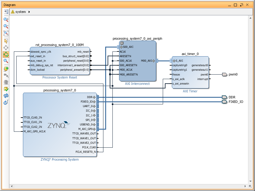
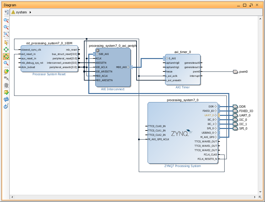
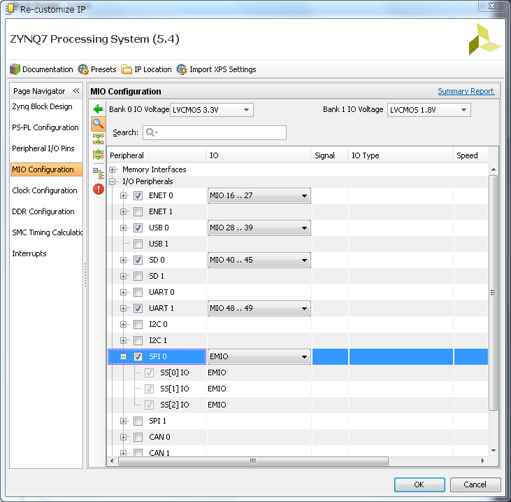
  20. So, below my simple Zynq block design. Now, I have to enable SPI port. Double click on 'Zynq processing system', go to 'MIO Configuration' and enable 'SPI0' port. As you can see it can only have maximum 3 Slave Select (or Chip Select) pin and sometimes its not enough.
  21. zynq14_8

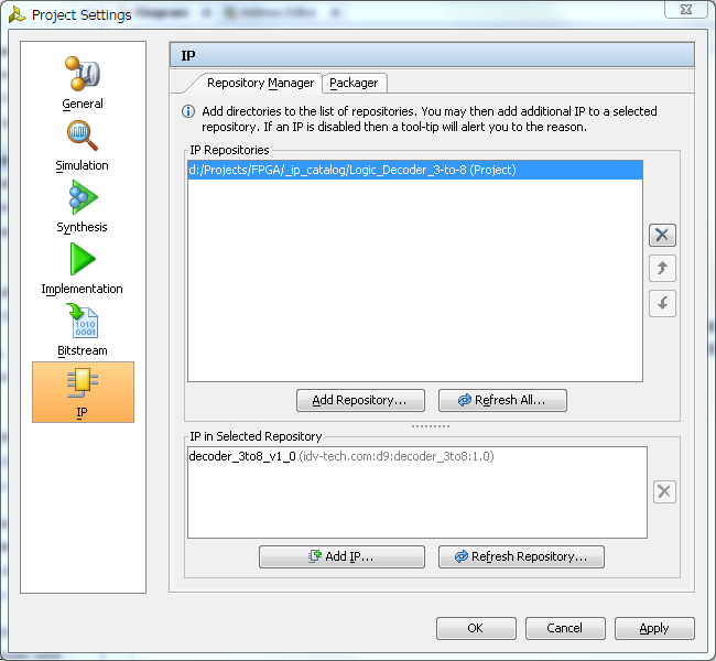
  22. Next we need to add our 3-to-8 decoder module to block diagram, but before we can do it, we must add it's repository to our project IP manager. So, in a 'Tools' menu select 'Project Settings' and then click on 'IP' icon.
  23. In 'IP' management dialog click on 'Add Repository...' button and specify our decoder IP project folder. Vivado will scan it, should find decoder IP and add it in found IP list. Click 'Apply' and then 'Ok' to close dialog.
  24. zynq14_9

  25. We can add decoder IP to our block diagram. Click on 'Add IP', typo decoder IP name and add it.
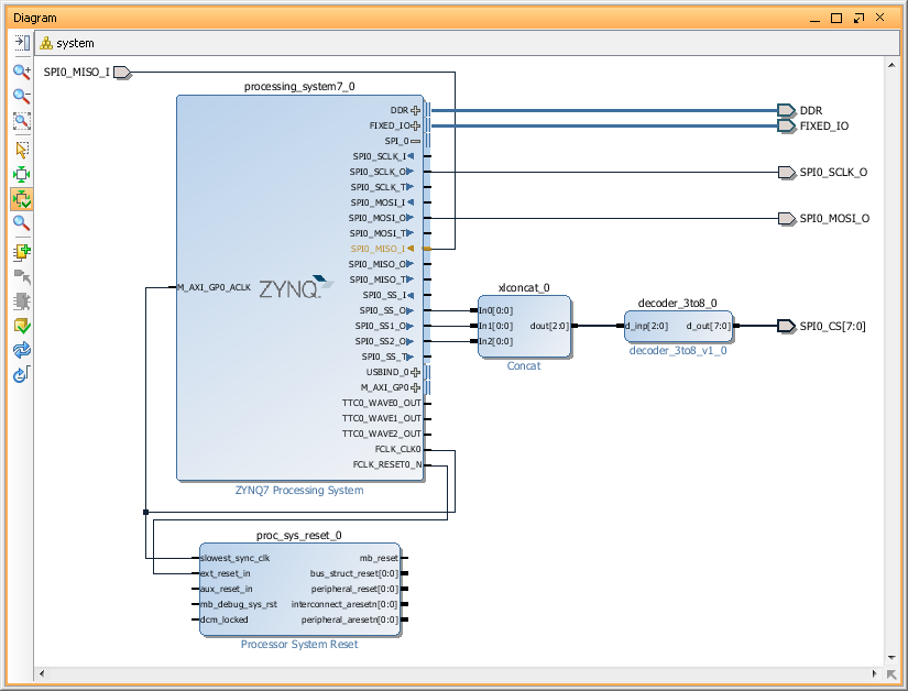
  26. Now we have to connect 3 SPI SS outputs to our decoder input, but we can't. Problem is that decoder inputs treated as a 'bus' and SPI SS outputs as individual 'wires'. One of the possible solution is to concatenate individual wires. In order to do it add Xilinx 'Concat' IP and modify it, so it will have 3 inputs.
  27. zynq14_10

  28. Now we should be able to connect all blocks together. Specifically, connect SPI0_SS0, SPI0_SS1 and SPI0_SS2 to 'Concat' block input 0,1 and 2. Them, connect 'Concat' output to our 3-to-8 decoder IP and finally make decoder outputs 'External'. I will also rename output port to 'SPI0_CS'.
  29. zynq14_11

  30. This is basically it. Now we have to create 'constraints' file and specify in it Zynq PACKAGE_PIN for some or all pins of the 'SPI_CS0' port. For example you may want to export only 4 CS pins. Something like this:
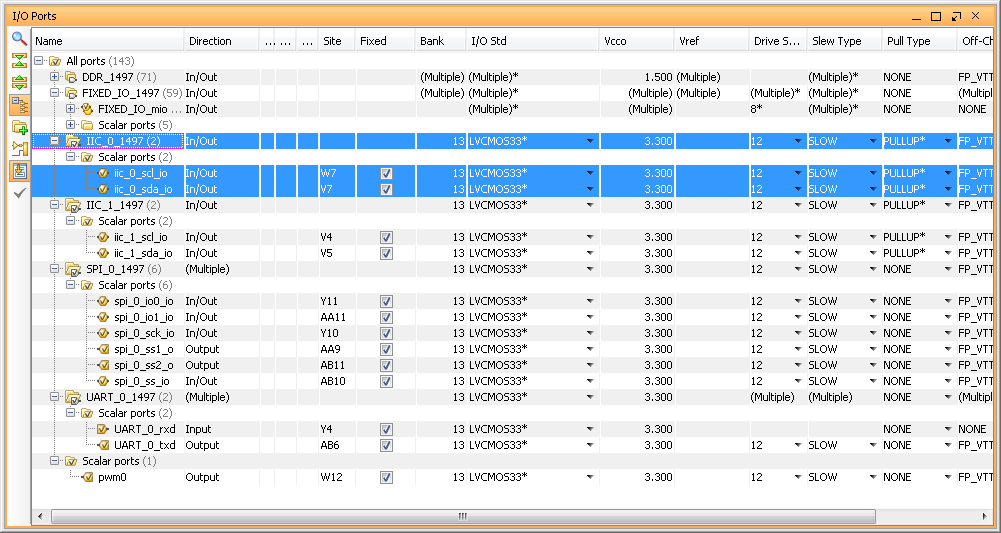
  31. set_property IOSTANDARD LVCMOS33 [get_ports SPI0_SCLK]
    set_property IOSTANDARD LVCMOS33 [get_ports SPI0_MISO]
    set_property IOSTANDARD LVCMOS33 [get_ports SPI0_MOSI]
    set_property IOSTANDARD LVCMOS33 [get_ports SPI0_CS[0]]
    set_property IOSTANDARD LVCMOS33 [get_ports SPI0_CS[1]]
    set_property IOSTANDARD LVCMOS33 [get_ports SPI0_CS[2]]
    set_property IOSTANDARD LVCMOS33 [get_ports SPI0_CS[3]]
    
    set_property PACKAGE_PIN AA9 [get_ports SPI0_SCLK]
    set_property PACKAGE_PIN Y10 [get_ports SPI0_MISO]
    set_property PACKAGE_PIN AA11 [get_ports SPI0_MOSI]
    set_property PACKAGE_PIN W12 [get_ports SPI0_CS[0]]
    set_property PACKAGE_PIN W11 [get_ports SPI0_CS[1]]
    set_property PACKAGE_PIN V10 [get_ports SPI0_CS[2]]
    set_property PACKAGE_PIN W8 [get_ports SPI0_CS[3]]
    
  32. Later, in a software project, you will need to enable special option for SPI driver to use 'Slave Select' pins as encoded address. But that is part of another tutorial, but this one finished. Good luck!

Howto export Zynq peripherals(I2C, SPI, UART and etc) to PMOD connectors of ZedBoard using Vivado 2013.4

This is the small howto describing export of some peripherals on ZedBoard's PMOD connectors.
ZedBoard have some, so called, FIXED_IO connections, which is hardwired to DDR memory, QSPI flash memory, Ethernet and etc. It also export Zynq UART1 to J14 connector. So, we don't have much of the Zynq MIO pin's available left, but got plenty of Zynq EMIO pins. Also, just 1 of the ZedBoard's PMOD connected to PS - JE1 PMOD, the rest connected to PL. So, I will export SPI1 to JE1 PMOD (using MIO), SPI0 to JA1 PMOD, both I2C0 and I2C1 to JD1 PMOD and PS UART0 to JC1 PMOD. I will also create and export single PWM signal to JC1 PMOD.

  1. Let's start with creating new project in Vivado 2013.4 and lets called ZedBoard, type 'RTL Project', don't add any VHDL/Verilog sources or IP. On 'Default Part' page, select your board type and revision. Finish project creation.
    We will be presented with default project view, similar to screenshot below.
  2. zynq11_01

    zynq11_02

    zynq11_03

  3. Next step is to create new 'Block Design' - let's name it 'system'.
  4. zynq11_04

  5. Use 'Add IP' button to add Xilinx IP blocks to our new block design. We will need to add a few of blocks, but lets do it step by step. First add 'Zynq7 Processing System'
  6. zynq11_06_1

  7. Next, click on 'Run Block Automation' link on a top green bar to apply 'Board Preset' for our ZedBoard and to automatically connect FIXED_IO and DDR. Once it done you will see DDR and FIXED_IO port created on in our Block Design.
  8. zynq11_07

    zynq11_08

  9. Add 'AXI Timer' IP block for our PWM signal.
  10. zynq11_09

  11. Next, run "Connection Automation" - it will add for us all IP block required by 'AXI Timer' and create all required connections. You can optimize Block Design layout by click on 'Regenerate Layout' button.
  12. zynq11_10

    zynq11_11

  13. Now we need to make our PWM signal external. To do it - 'left' click in 'pwm0' pin of 'axi_timer_0' block to select it and then 'right' to open 'pin' config menu and select 'Make External' option. It will create 'pwm0' port and connection to it.
  14. zynq11_12

  15. Let's configure Zynq PS UART, SPI and I2C - double click on 'Zynq Processing System' to open it 'Customization' window.
  16. zynq11_13

  17. In a 'MIO Configuration' expand 'I/O Peripherals' tree and enable 'UART0', both I2C and both SPI. And set 'EMIO' for UART0, both I2C and SPI0. But for SPI1 select 'MIO 10..15' option. This pin's routed to PS PMOD on ZedBoard, which is JE1 PMOD. After we make all the changes, we can save changes and close this window by hitting 'Ok' button.
  18. zynq11_14

  19. Notice that our Zynq7 PS block on diagram got UART0, SPI0 and I2C0 and I2C1 ports. SPI1 is missing because it included in a Fixed_IO port.
  20. zynq11_15

  21. Make UART0, SPI0 and both I2C ports external.
  22. zynq11_16

  23. We are done with 'Block Design' - save it.
  24. Now we have to create 'HDL Wrapper' for our 'Block Design'. We can do it by selecting our 'system' block design in a 'Design Sources' list of 'Sources' window and 'Creat HDL wrapper' thru 'right' mouse click menu. Let Vivado manage it.
  25. zynq11_17

  26. Run Synthesis.
  27. Run Implementation.
  28. If we will try to generate Bitstream now it will fail, because we didn't set which of our ports goes to which Zynq pin. So, lets configure it now.
    Open implemented design.
  29. Now, we can manually create constraints file with settings for each pin or we can use Vivado GUI to generate constraints file. Let's use Vivado this time - open 'I/O Ports' window thru Vivado top level 'Window' menu.
  30. In 'I/O Ports' menu we have to select, so called, 'Site' for each port. 'Site' is Zynq package pin and we can find correlation between 'Sites' and PMOD pins of ZedBoard in ' ZedBoard Hardware User's Guide' from ZedBoard.com
  31. We also have to set 'I/O Standard' - which is supply level on a 'Site'.
  32. I2C ports also requires to be pulled-up and you can set 'Pull Type' for each 'Site' here, but it a very good idea to verify voltage/current requirements for your particular design, before you enable it.
  33. zynq11_17

  34. Save Project. Vivado will ask you for a name for a new constraints file. Let's call it 'zedboard_constraints.xdc' - below listing of that file in my case.
    Vivado will also detect changes in a project and will aks if you want to update Synthesis/Implementation or force it to accept changes without regeneration. Let's just regenerate whole thing just to be sure.
  35. set_property IOSTANDARD LVCMOS33 [get_ports iic_0_scl_io]
    set_property IOSTANDARD LVCMOS33 [get_ports iic_0_sda_io]
    set_property IOSTANDARD LVCMOS33 [get_ports iic_1_scl_io]
    set_property IOSTANDARD LVCMOS33 [get_ports iic_1_sda_io]
    set_property IOSTANDARD LVCMOS33 [get_ports spi_0_io0_io]
    set_property IOSTANDARD LVCMOS33 [get_ports spi_0_io1_io]
    set_property IOSTANDARD LVCMOS33 [get_ports spi_0_sck_io]
    set_property IOSTANDARD LVCMOS33 [get_ports spi_0_ss1_o]
    set_property IOSTANDARD LVCMOS33 [get_ports spi_0_ss2_o]
    set_property IOSTANDARD LVCMOS33 [get_ports spi_0_ss_io]
    set_property IOSTANDARD LVCMOS33 [get_ports UART_0_rxd]
    set_property IOSTANDARD LVCMOS33 [get_ports UART_0_txd]
    set_property IOSTANDARD LVCMOS33 [get_ports pwm0]
    set_property PULLUP true [get_ports iic_0_scl_io]
    set_property PULLUP true [get_ports iic_0_sda_io]
    set_property PULLUP true [get_ports iic_1_scl_io]
    set_property PULLUP true [get_ports iic_1_sda_io]
    set_property PACKAGE_PIN W12 [get_ports pwm0]
    set_property PACKAGE_PIN AB6 [get_ports UART_0_txd]
    set_property PACKAGE_PIN Y4 [get_ports UART_0_rxd]
    set_property PACKAGE_PIN W7 [get_ports iic_0_scl_io]
    set_property PACKAGE_PIN V7 [get_ports iic_0_sda_io]
    set_property PACKAGE_PIN Y11 [get_ports spi_0_io0_io]
    set_property PACKAGE_PIN AA11 [get_ports spi_0_io1_io]
    set_property PACKAGE_PIN Y10 [get_ports spi_0_sck_io]
    set_property PACKAGE_PIN AA9 [get_ports spi_0_ss1_o]
    set_property PACKAGE_PIN AB11 [get_ports spi_0_ss2_o]
    set_property PACKAGE_PIN AB10 [get_ports spi_0_ss_io]
    set_property PACKAGE_PIN V4 [get_ports iic_1_scl_io]
    set_property PACKAGE_PIN V5 [get_ports iic_1_sda_io]

  36. Generate Bitstream.
  37. Congratulations, you can now 'Export Hardware to SDK' and use it in software projects!