This is the small howto describing export of some peripherals on ZedBoard's PMOD connectors.
ZedBoard have some, so called, FIXED_IO connections, which is hardwired to DDR memory, QSPI flash memory, Ethernet and etc. It also export Zynq UART1 to J14 connector. So, we don't have much of the Zynq MIO pin's available left, but got plenty of Zynq EMIO pins. Also, just 1 of the ZedBoard's PMOD connected to PS - JE1 PMOD, the rest connected to PL. So, I will export SPI1 to JE1 PMOD (using MIO), SPI0 to JA1 PMOD, both I2C0 and I2C1 to JD1 PMOD and PS UART0 to JC1 PMOD. I will also create and export single PWM signal to JC1 PMOD.
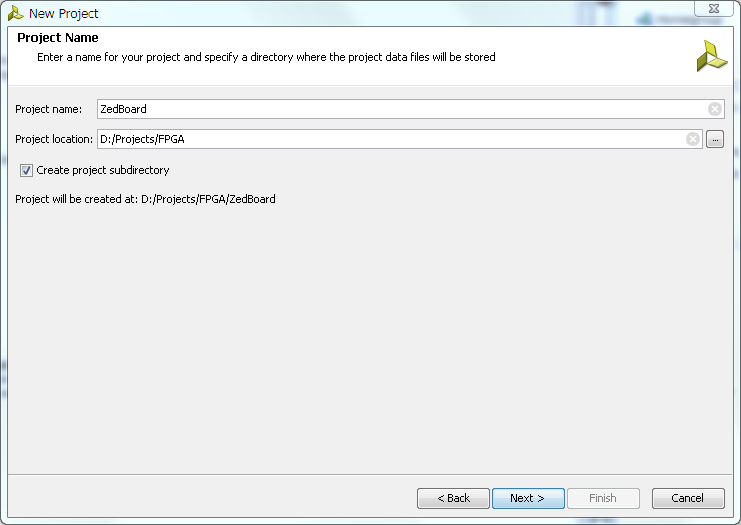
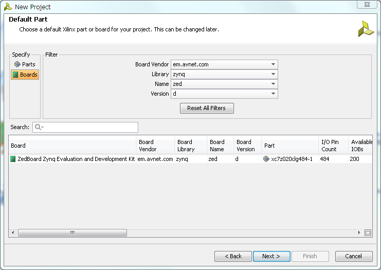
- Let's start with creating new project in Vivado 2013.4 and lets called ZedBoard, type 'RTL Project', don't add any VHDL/Verilog sources or IP. On 'Default Part' page, select your board type and revision. Finish project creation.
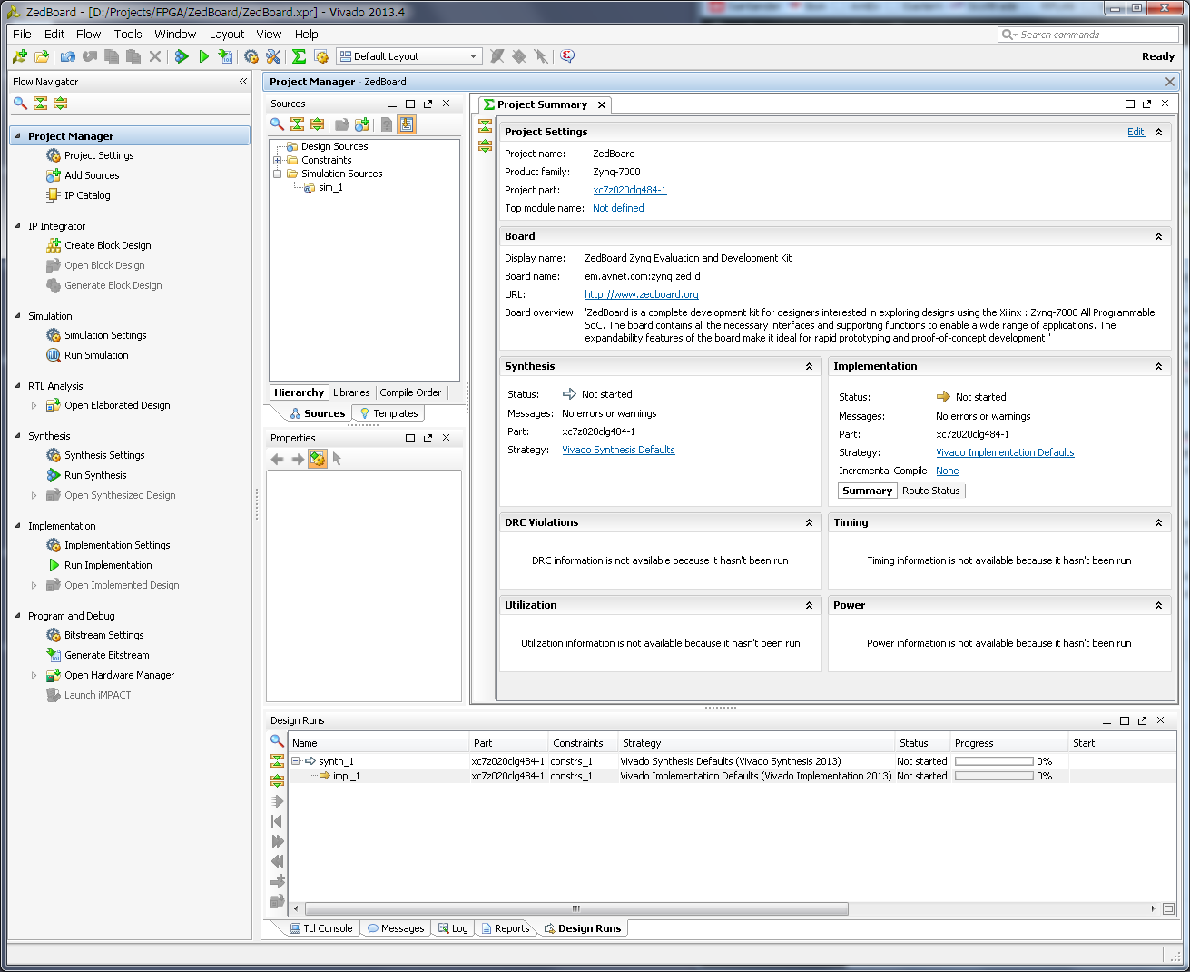
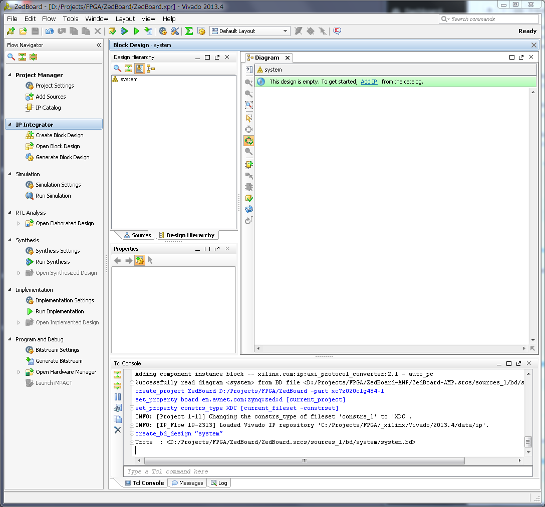
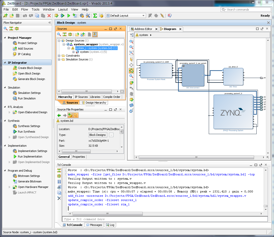
We will be presented with default project view, similar to screenshot below. - Next step is to create new 'Block Design' - let's name it 'system'.
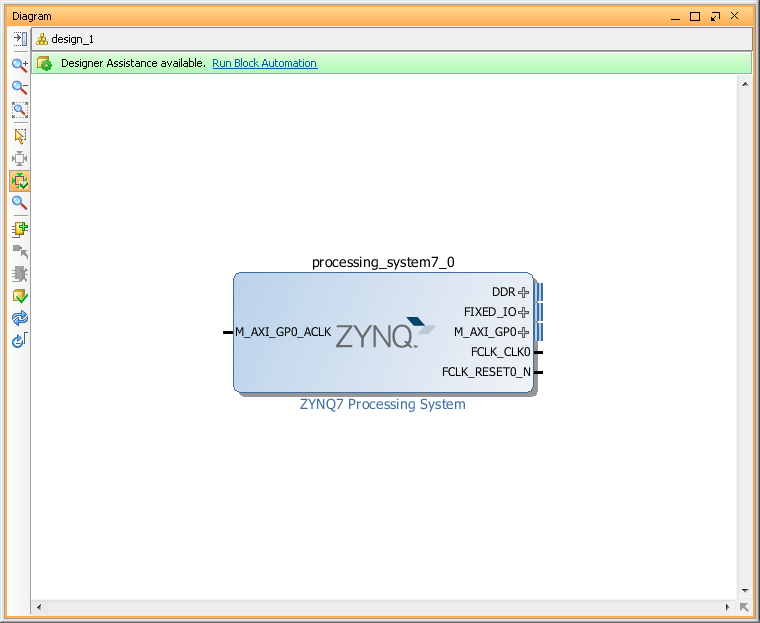
- Use 'Add IP' button to add Xilinx IP blocks to our new block design. We will need to add a few of blocks, but lets do it step by step. First add 'Zynq7 Processing System'
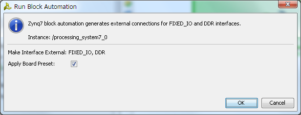
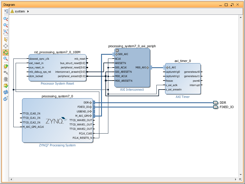
- Next, click on 'Run Block Automation' link on a top green bar to apply 'Board Preset' for our ZedBoard and to automatically connect FIXED_IO and DDR. Once it done you will see DDR and FIXED_IO port created on in our Block Design.
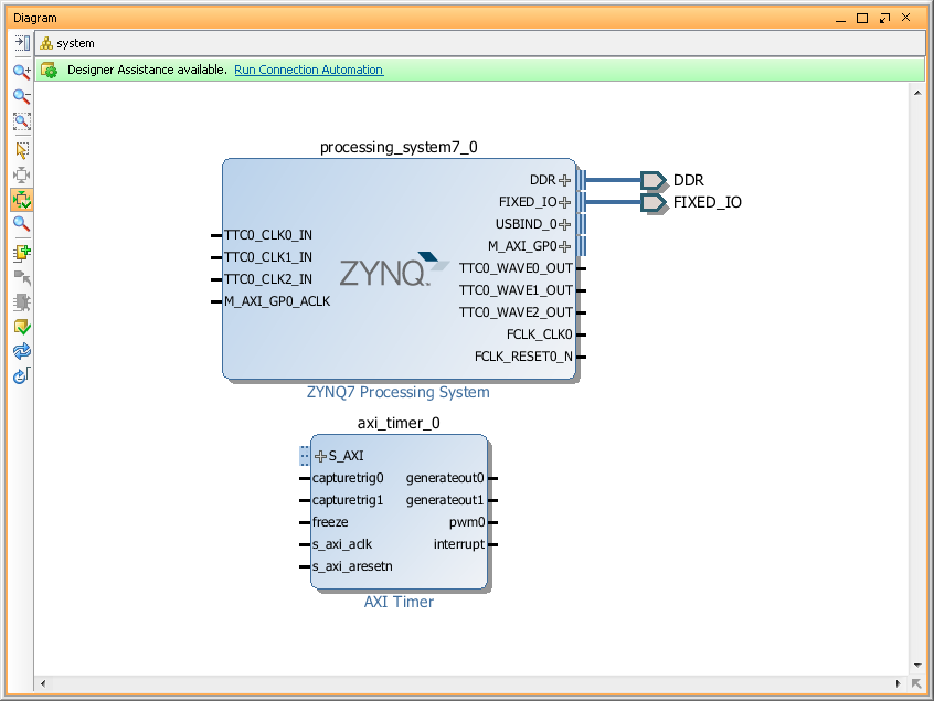
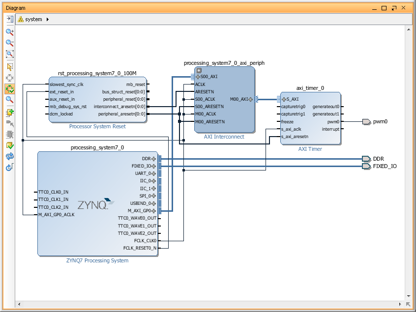
- Add 'AXI Timer' IP block for our PWM signal.
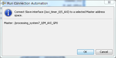
- Next, run "Connection Automation" - it will add for us all IP block required by 'AXI Timer' and create all required connections. You can optimize Block Design layout by click on 'Regenerate Layout' button.
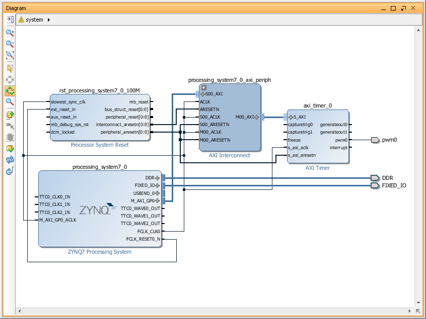
- Now we need to make our PWM signal external. To do it - 'left' click in 'pwm0' pin of 'axi_timer_0' block to select it and then 'right' to open 'pin' config menu and select 'Make External' option. It will create 'pwm0' port and connection to it.
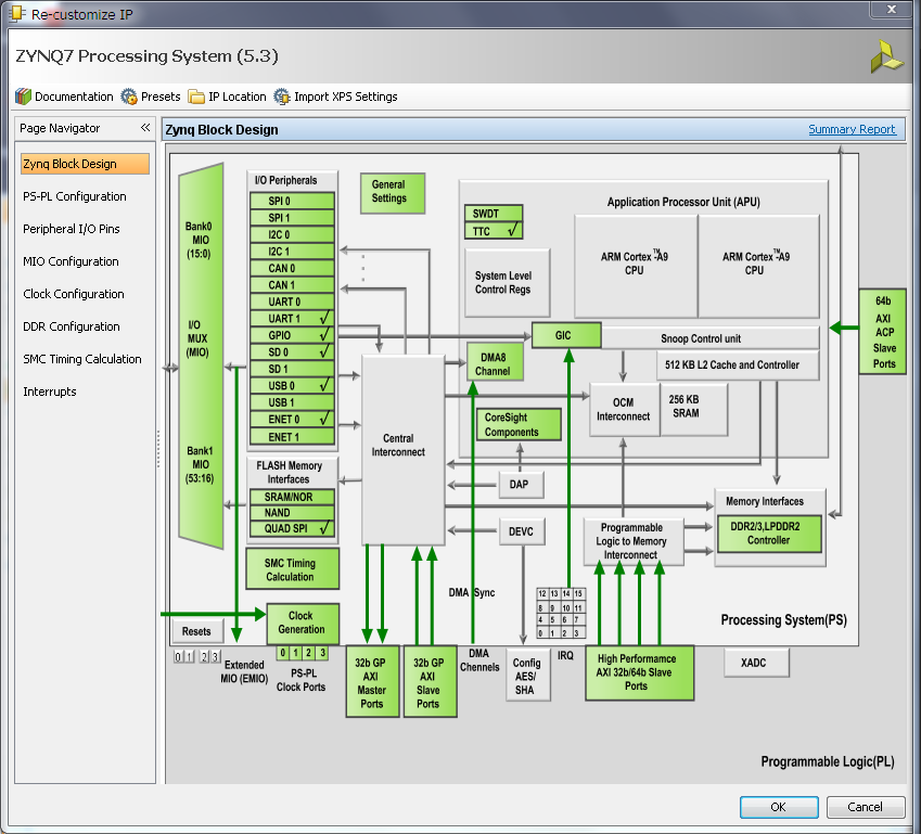
- Let's configure Zynq PS UART, SPI and I2C - double click on 'Zynq Processing System' to open it 'Customization' window.
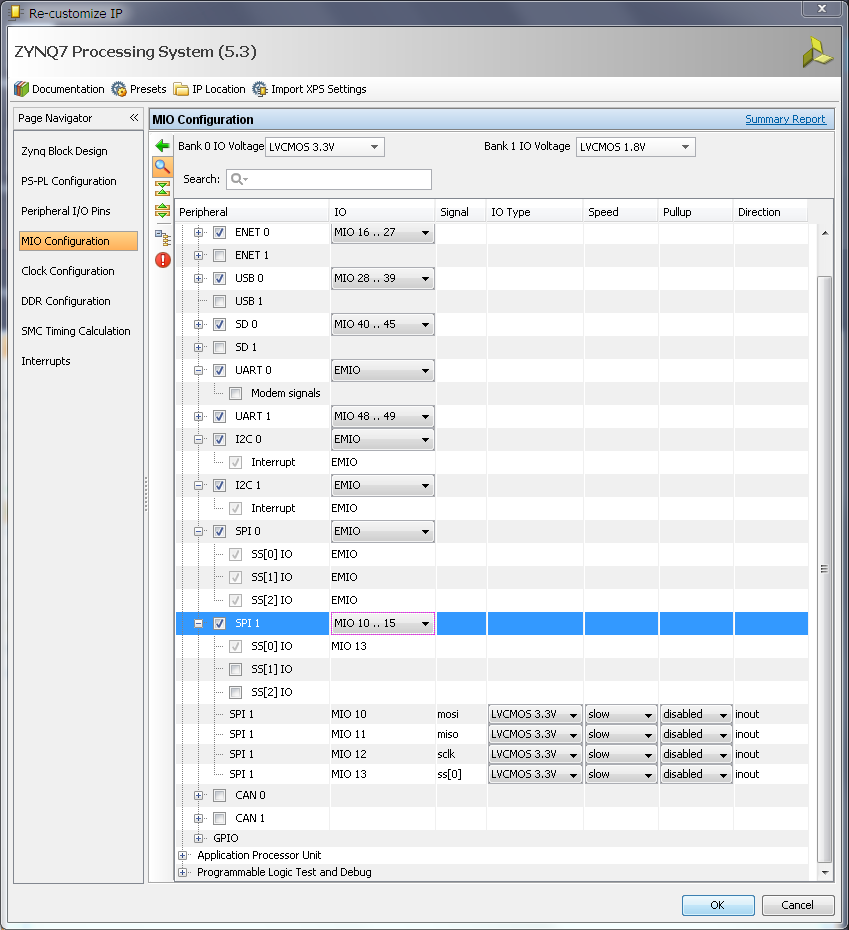
- In a 'MIO Configuration' expand 'I/O Peripherals' tree and enable 'UART0', both I2C and both SPI. And set 'EMIO' for UART0, both I2C and SPI0. But for SPI1 select 'MIO 10..15' option. This pin's routed to PS PMOD on ZedBoard, which is JE1 PMOD. After we make all the changes, we can save changes and close this window by hitting 'Ok' button.
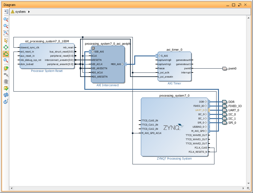
- Notice that our Zynq7 PS block on diagram got UART0, SPI0 and I2C0 and I2C1 ports. SPI1 is missing because it included in a Fixed_IO port.
- Make UART0, SPI0 and both I2C ports external.
- We are done with 'Block Design' - save it.
- Now we have to create 'HDL Wrapper' for our 'Block Design'. We can do it by selecting our 'system' block design in a 'Design Sources' list of 'Sources' window and 'Creat HDL wrapper' thru 'right' mouse click menu. Let Vivado manage it.
- Run Synthesis.
- Run Implementation.
- If we will try to generate Bitstream now it will fail, because we didn't set which of our ports goes to which Zynq pin. So, lets configure it now.
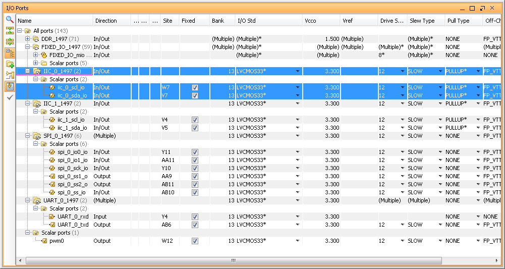
Open implemented design. - Now, we can manually create constraints file with settings for each pin or we can use Vivado GUI to generate constraints file. Let's use Vivado this time - open 'I/O Ports' window thru Vivado top level 'Window' menu.
- In 'I/O Ports' menu we have to select, so called, 'Site' for each port. 'Site' is Zynq package pin and we can find correlation between 'Sites' and PMOD pins of ZedBoard in ' ZedBoard Hardware User's Guide' from ZedBoard.com
- We also have to set 'I/O Standard' - which is supply level on a 'Site'.
- I2C ports also requires to be pulled-up and you can set 'Pull Type' for each 'Site' here, but it a very good idea to verify voltage/current requirements for your particular design, before you enable it.
- Save Project. Vivado will ask you for a name for a new constraints file. Let's call it 'zedboard_constraints.xdc' - below listing of that file in my case.
Vivado will also detect changes in a project and will aks if you want to update Synthesis/Implementation or force it to accept changes without regeneration. Let's just regenerate whole thing just to be sure. - Generate Bitstream.
- Congratulations, you can now 'Export Hardware to SDK' and use it in software projects!

set_property IOSTANDARD LVCMOS33 [get_ports iic_0_scl_io]
set_property IOSTANDARD LVCMOS33 [get_ports iic_0_sda_io]
set_property IOSTANDARD LVCMOS33 [get_ports iic_1_scl_io]
set_property IOSTANDARD LVCMOS33 [get_ports iic_1_sda_io]
set_property IOSTANDARD LVCMOS33 [get_ports spi_0_io0_io]
set_property IOSTANDARD LVCMOS33 [get_ports spi_0_io1_io]
set_property IOSTANDARD LVCMOS33 [get_ports spi_0_sck_io]
set_property IOSTANDARD LVCMOS33 [get_ports spi_0_ss1_o]
set_property IOSTANDARD LVCMOS33 [get_ports spi_0_ss2_o]
set_property IOSTANDARD LVCMOS33 [get_ports spi_0_ss_io]
set_property IOSTANDARD LVCMOS33 [get_ports UART_0_rxd]
set_property IOSTANDARD LVCMOS33 [get_ports UART_0_txd]
set_property IOSTANDARD LVCMOS33 [get_ports pwm0]
set_property PULLUP true [get_ports iic_0_scl_io]
set_property PULLUP true [get_ports iic_0_sda_io]
set_property PULLUP true [get_ports iic_1_scl_io]
set_property PULLUP true [get_ports iic_1_sda_io]
set_property PACKAGE_PIN W12 [get_ports pwm0]
set_property PACKAGE_PIN AB6 [get_ports UART_0_txd]
set_property PACKAGE_PIN Y4 [get_ports UART_0_rxd]
set_property PACKAGE_PIN W7 [get_ports iic_0_scl_io]
set_property PACKAGE_PIN V7 [get_ports iic_0_sda_io]
set_property PACKAGE_PIN Y11 [get_ports spi_0_io0_io]
set_property PACKAGE_PIN AA11 [get_ports spi_0_io1_io]
set_property PACKAGE_PIN Y10 [get_ports spi_0_sck_io]
set_property PACKAGE_PIN AA9 [get_ports spi_0_ss1_o]
set_property PACKAGE_PIN AB11 [get_ports spi_0_ss2_o]
set_property PACKAGE_PIN AB10 [get_ports spi_0_ss_io]
set_property PACKAGE_PIN V4 [get_ports iic_1_scl_io]
set_property PACKAGE_PIN V5 [get_ports iic_1_sda_io]
hello
good and fast ...
but I have a problem... I made it, and in sdk wanted to launch "hello world" , just for test
and nothing appears on terminal.Anyone has an idea?
thanks
Tutorial found very useful. Thank you so much. I need to know the SDK part as well. After exporting hardware to SDK if I want to do a Serial communication using UART0 through the PMOD Connectors what has to be done. How to select UART0 and UART1 or both and how to transmit and receive through this seperately.
Please Give a suggestion
Thanks for the helpful post. I came here looking for enabling UART0 for CPU1 in AMP mode for Zynq ZC706 (not Zedboard). I am able to connect UART0 to EMIO and mark it as External. I am using Vivado 2014.1 and can build the bitstream.
Question is - where is this EMIO available on the Zynq ZC706 board and how will I get the Uart Tx/Rx? Via some custom header on the board or multiplexed on the USB-UART cable itself? Thanks a lot!
You tide your 'external signals' to so called 'package_pins' of Zynq in a constrains file. For example:
set_property -dict {PACKAGE_PIN AB2 IOSTANDARD LVCMOS33} [get_ports serial0_tx]
Which put serial0_tx signal to Zynq package pin AB2 and set it voltage standard to LowVoltage CMOS 3.3V. And which package_pin goes to what connector you find in a board documentation.
Thanks much. I didn't realize that this is how an EMIO can be routed to the FPGA pin. Thanks. Now, I still can't figure out if my Zynq ZC706 board has any potential header that I can use with some package pin to get my UART Tx/Rx going. You obviously use a Zedboard so wouldn't know.
http://www.xilinx.com/support/documentation/boards_and_kits/zynq-7000/zc706-schematic-xtp215-rev1-1.pdf
I am surprised that for a two-core CPU, there isn't better support for two UARTs and that no one is talking about this either.
Hi everybody,
Please, somebody could tell me how to add a hdl design and create peripherals in vivado HLS.???
As i am in learning stage, i tried to add design to see outputs on logic analyzer but i failed , i did not get any proper document on adding a hdl in vivado.
whats are the steps to add design and see output on analyzer from scratch????
please somebody help me out. Thanks in advance.
I'm working with a Zynq zedboard in vivado.
Try to google it - I was able to find some useful tutorials on HLS.
Hello. I am trying to read a force sensor (which is connected to Zedboard via Digilent PMODAD1) through spi communication. I created block design as you said but after that I don't know what should I do in SDK? How can I read sensor values? thank you in advenced.
Hello!
I followed your tutorial and when generate bit stream, I got the ERROR :
--------------------------------------------------------------------------------
ERROR: [DRC 23-20] Rule violation (NSTD-1) Unspecified I/O Standard - 13 out of 143 logical ports use I/O standard (IOSTANDARD) value 'DEFAULT', instead of a user assigned specific value. This may cause I/O contention or incompatibility with the board power or connectivity affecting performance, signal integrity or in extreme cases cause damage to the device or the components to which it is connected. To correct this violation, specify all I/O standards. This design will fail to generate a bitstream unless all logical ports have a user specified I/O standard value defined. To allow bitstream creation with unspecified I/O standard values (not recommended), use this command: set_property SEVERITY {Warning} [get_drc_checks NSTD-1]. NOTE: When using the Vivado Runs infrastructure (e.g. launch_runs Tcl command), add this command to a .tcl file and add that file as a pre-hook for write_bitstream step for the implementation run. Problem ports: pwm0, iic_1_scl_io, iic_1_sda_io, spi_0_io0_io, spi_0_io1_io, spi_0_sck_io, spi_0_ss1_o, spi_0_ss2_o, spi_0_ss_io, iic_0_scl_io, iic_0_sda_io, UART_0_rxd, UART_0_txd.
------------------------------------------------------------------------------------
I've tried a lot about this but still cannot figure it out.I'm using digilent ZYBO board.
Thanks for your excellent tutorial.
Hi d9,
I was trying to map the pins for I2C ports, but there were 6 one-direction ports(i,o,t for scl, sda) under my iic_0. So I was wondering if you know how to combine them into 2 inout ports, like the one in your screenshot above. Thanks!
Best,
xyhz
xyhz12345: Just select whole port, not individual signals and make it "external".
Tutorial found very useful. Thank you so much. I need to know the SDK part as well. After exporting hardware to SDK if I want to do a Serial communication using UART0 through the PMOD Connectors what has to be done. How to select UART0 and UART1 or both and how to transmit and receive through this seperately.
Please Give a suggestion
Hello d9,
Can you tell me if I need to work on any others steps for SP1. I have enabled I2C0 pins in MIO 50, 51 and am not able to figure out which pins to use to connect in Zynq 7000 SoC ZC702. Can you please help me with this?
Thank You